
I was asked to design and build the gear and drive mechanism for a 6 foot clock. The clock had an hour and a minute hand and needed to move in both the clockwise and anti-clockwise direction. This was not a “realtime clock” and needed to move visibly fast.
I decided to use wood clock gears with a motor drive for the sake of simplicity. This build was definitely more out of my comfort zone than usual but proved to be a fun and educational experience. Part 1 goes over the design of the gears. Part 2 will cover the physical build and Part 3 the electrical design and final build.
Preliminary Design
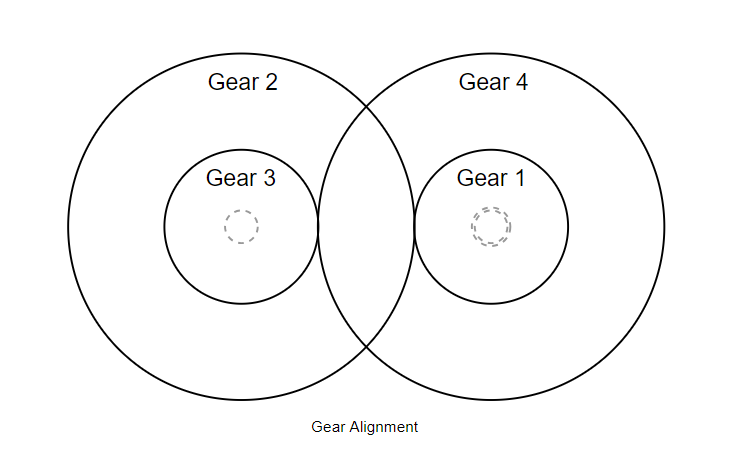
The design called for a minute and hour hand so the target gear ratio was 1:12 (since it’s a 12 hour clock). A clock requires the output shafts to be aligned, meaning I needed to create a compound gear configuration of four gears with two sharing a shaft each. The shaft spacing between each gearset needs to be the same. I chose to use spur gears since they are the most appropriate for my design and are also very easy to manufacture.
Calculating Gear Ratios
I set the minimum number of teeth to 10 since I only wanted to use four gears and based on the scale of the design. This made the gear ratio 10:120 (which is still the same). I then multiplied 10 by the square root of 12 (since that’s the gear ratio I’m targeting for each) to yield a new compound gear ratio of 10:35:120, which can be represented as 10:35 and 35:120.
Because I didn’t want to deal with a 120 teeth wooden gear, I needed to find a common denominator with which to divide the second set of gears. I bumped up the 35 to 36 and divided the right side by 3 to yield a final result of 10:36 and 12:40. This yields a gear ratio of 1:12
![\[ 10*12:36*40\\ \]](https://paulbupejr.com/wp-content/ql-cache/quicklatex.com-6b22d869fa062b8c96eebc937987f437_l3.png "Rendered by QuickLaTeX.com")
![\[ 120:1440\\ \]](https://paulbupejr.com/wp-content/ql-cache/quicklatex.com-bbcc30725659430cb1dcb5f603d1131d_l3.png "Rendered by QuickLaTeX.com")
![\[ 1:12 \]](https://paulbupejr.com/wp-content/ql-cache/quicklatex.com-3fe2c487b535c434eaa693e7d0ea822e_l3.png "Rendered by QuickLaTeX.com")
Gear Design
Up to this point I had the following information:
- The smallest gear has 10 teeth.
- Both gear pairs needed to have the same center distance (C).
- I wanted the pitch diameter (the effective diameter at which two gears mate) of the smallest gear to be around 1.5 inches.
The following image from Groschopp is a useful reference for gear terms and meanings.
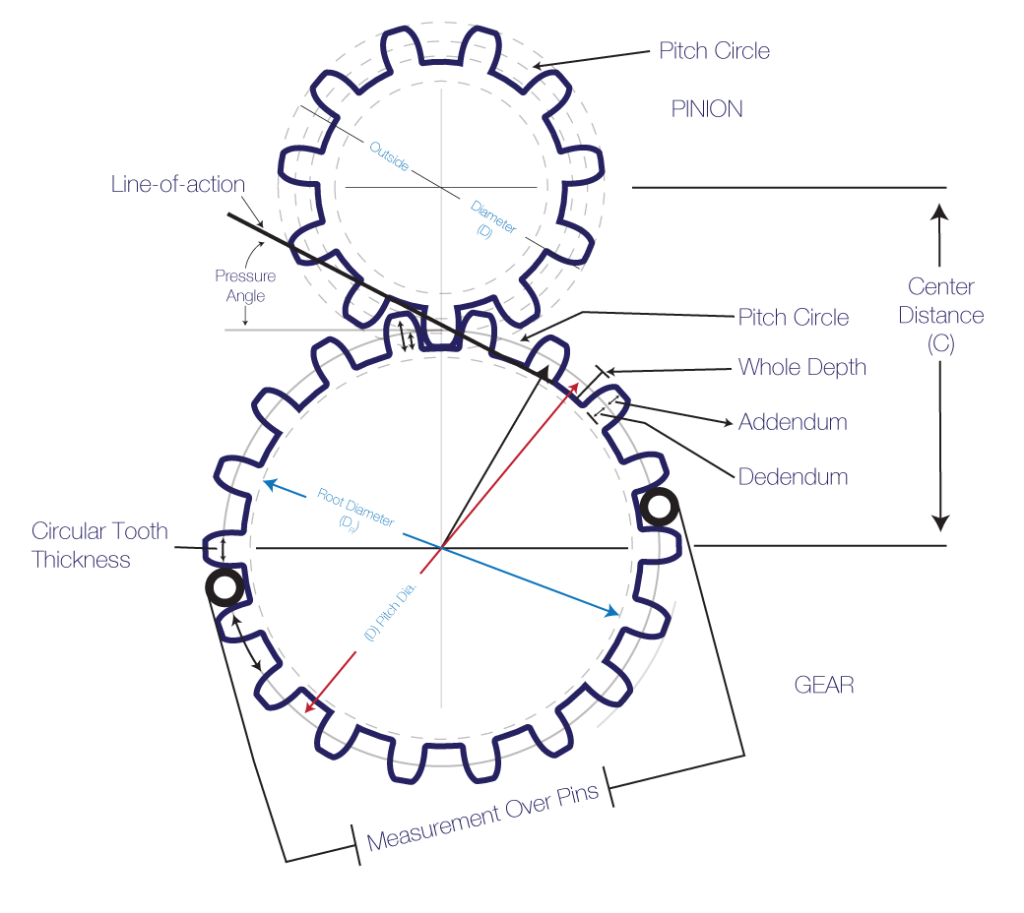
The most important value I had to calculate was the module (m) of the gears. The module is the ratio of the pitch diameter (d) to the number of teeth (N):
![\[ m = \frac{d}{N} \]](https://paulbupejr.com/wp-content/ql-cache/quicklatex.com-e4219d4decd0b2df95259e30dae4df94_l3.png "Rendered by QuickLaTeX.com")
Two gears must have the same module in order to properly mate. With a pitch diameter of 1.5 and 10 teeth, the module of the first gear is  . Using the module formula, the pitch diameter of the second gear has to be
  . The center distance, C, is given by
![\[ C = \frac{d_1 + d_2}{2} \]](https://paulbupejr.com/wp-content/ql-cache/quicklatex.com-c9cd4659b4348087d30806ef4ceef7ec_l3.png "Rendered by QuickLaTeX.com")
which evaluates to  . Using this information and the fact that the diametral pitch is the inverse of the module, the rest of the gears were calculated and designed in SolidWorks. In the final design I ended up increasing the pitch diameter to 1.52in.

Notes
At this point I’m fairly happy with the design. Since I’m designing wood clock gears I needed to make sure everything was scaled large enough to handle the stresses of the clock hands. Unfortunately I don’t know just how heavy the clock hands will be so the design assumes “reasonable worst case” scenarios.
Thank you!! This is fantastic!